Doctoral Dissertation
Coherent manipulation of a single spin in SiC
The presented results in the following chapter were partially achieved by an international collaboration with the Synergetic Innovation Center of Quantum Information and Quantum Physics, University of Science and Technology of China and is part of two shared publications:
M. Widmann, S.-Y. Lee, J. Wrachtrup, et al., Coherent control of single spins in silicon carbide at ambient condition, Nat. Mater. (2015) 14 (Widmann et al., 2015)
L.-P. Yang, C. Burk, M. Widmann, S.-Y. Lee, J. Wrachtrup, N. Zhao, Electron spin decoherence in silicon carbide nuclear spin bath, Phys. Rev. B. 90 (2014). (Yang et al., 2014)
Introduction
Motivated by the single spin detection in silicon carbide presented in the previous chapter (Section cw-ODMR), the next important step towards a silicon carbide based quantum device is the demonstration of more advanced spin manipulation, namely coherent control of the spin state. The ability to control the quantum state of a single electron is the core of spin based quantum applications. The following chapter is dedicated to this task: it will be shown that coherent control of a single spin is feasible at room temperature. This is shown by the demonstration of spin Rabi oscillations under various rf driving strengths and the coherent properties are further investigated by spin-echo experiments.
Spin-Rabi Oscillations
The fundamental basis for full qbit control is to manipulate quantum states in a coherent fashion. Coherent manipulation of quantum state is a necessary prerequisite for both quantum gates (eg. by coupling to a proximal nuclear spin (Jiang et al., 2009; Neumann et al., 2010)) and for more complex pulse sequences for sensing applications (Häberle et al., 2017).
The life time and the coherence time, are limiting factors for the length of the pulse sequences. The achieved coherence times are discussed in more detail in Section 3.4. In order to test if can be coherently controlled it is necessary to test if the spin can be initialized and if the spin state can be altered in a controlled way. In order to observe Rabi oscillations between the magnetic spin sublevels of in 4H-SiC the degeneracy has to be lifted, as each of the states and states are degenerated. That can be done by applying a magnetic field at . Three possible spin transition can be chosen in principle.
Because of the equal population within the -levels, only two transitions and can be used. To prove that coherent spin driving is possible, the is selected, but driving the spin in the is also possible. After the magnetic field alignment, the system is initialized via a laser pulse into . A lasting idle time allows the system to fully relax from the metastable state into the ground state.
After the ground state is polarized a rectangular rf pulse is applied to drive the transition. The spin state is subsequently read out by another laser pulse, which is also used for the next initialization. That sequence is repeated while increasing the length of the rf pulse up to .

Figure 3.1: a) Schematic of the pulse sequence for coherent spin driving. The spin is initialized into by a laser pulse, a fixed waiting time allows the system to decay into the ground state. A rf-pulse with variable length alters the spin populations before the spin state is read out by another laser pulse (which is also used as the initialization for the next rf manipulation). Adapted from ref. (Simin et al., 2017a). b) fluorescence response. c) Room temperature spin Rabi oscillation between transition of a single electron spin at various driving field strengths . To split the degeneracy of and a static magnetic field along -axis at G was applied. The spin signal is revealed by an integration of the pl response originating from the readout laser pulse within the first 60-120ns. The red curves are fits using an exponential decaying sinusoidal fit. The frequency values on top right side on each sub-plot are the extracted Rabi frequencies . Adapted from ref. (Widmann et al., 2015). d) Extracted Rabi frequencies () from c plotted as circles as a function of the converted rf-field () strength to the square root of the total rf power () which was applied to the copper wire, according to . The red line indicates a linear fit. Adapted from ref. (Widmann et al., 2015)
The obtained result is plotted in Figure 3.1b and is showing a long lasting oscillations of the spin state. Here, the spin state is oscillating with the rf-pulse length according to:
where specifies the difference in pl, the Rabi frequency and is the constant modeling the decay, and an offset. In order to confirm that the obtained oscillations originate from true single spin transitions, the rf driving strength was varied from to . When the Rabi frequency is plotted as a function of the converted square root of the rf driving strength a linear dependence is expected. As shown in Figure 3.1c a clear linear dependence is visible, and an unambiguous proof that a single spin is coherently controlled. The observed Rabi spin oscillations experience a decay, which is a clear indication for decoherence. The processes involved in the decoherence are discussed in more detail in Section 3.4. The upper fundamental limit, however, is given by the characteristic time constant T1.
Relaxation Time
Polarized spin system are subject to thermal equilibration. Hence they will not stay polarized for an infinite time. The spin will relax within a characteristic time, commonly known as T1 time (see Section Bloch Equations ). The reason for relaxation is the interaction between the spin with phonons, originating from lattice vibrations. Because of that interaction, such relaxation is often called spin-lattice relaxation. In other words, the T1 is a measure how fast the spin is depolarized.
As mentioned above, the spin T1-relaxation plays an important role, as it gives the upper limit for the time in which the spin-system can be used before its state is completely destroyed. In order to increase the spin life time, a reduction of the spin-phonon interaction is necessary, which can be achieved at low temperatures. To explore the properties at ambient condition, the spin-relaxation at room temperature is investigated in the following.
Theoretical Model

Figure 3.2: T1 relaxation rate model. Among the spin sublevels of the ground state of at axial . Magnetic spin sublevels are split by an axial . Arrows indicate the relaxation paths between the sublevels after steady state initialization with a laser beam. Adapted from ref. (Widmann et al., 2015).
Before the experimental data is presented, a theoretical model for the T1 spin relaxation for the is deduced. The first step is the determination of the steady-state polarization. It is commonly accepted the spin polarization is at least 80% in the ground state of , which was demonstrated in classical epr (Soltamov et al., 2012) after optical pumping. Because of that, it can be well approximated that all spins are polarized into the ground state after the spin is initialized. Other rates from the metastable to the ground state can be neglected, because they are fast ( (Fuchs et al., 2015)) compared to the expected long T1. As reported in ref. (Soltamov et al., 2012), the spins polarize into . Additionally the states are assumed to be equally populated as no magnetic resonance is observed in cw-driving.
The T1 relaxation rate can then be represented by a rate T1 as illustrated in Figure 3.2. The ground state populations can be described by the following rate model:
With considering the initial populations and the following solutions are obtained:
As the optical transitions are spin-conservative, a readout laser pulse will not affect the spin distribution in the excited state. Hence the sublevels in the excited state will keep the same spin populations as for those in ground state.
Once excited by the laser pulse, some of the excited states will experience non-radiative decays to the metastable state in the ns regime, whereas others will decay radiatively to the ground state. As this process is spin dependent, the rates from the excited state to the ground state are different for and . The unknown spin-dependent radiative transition rate can be expressed as , where . For the case where no rf pulse is applied, the photoluminescence intensity is given by:
For the case where rf pulse (-pulse) is applied to invert the spin distribution between and , the pl intensity is given by:
The difference between these intensities is then:
Here, it should be noted that the observed time constant is not T1 but is T1/2.
Experiment
The experimental conditions are the same as in Section 3.2. The magnetic field was aligned to the symmetry axis and the length of the -pulse was chosen according to the driving strength. The used pulse scheme is presented in Figure 3.3 a).
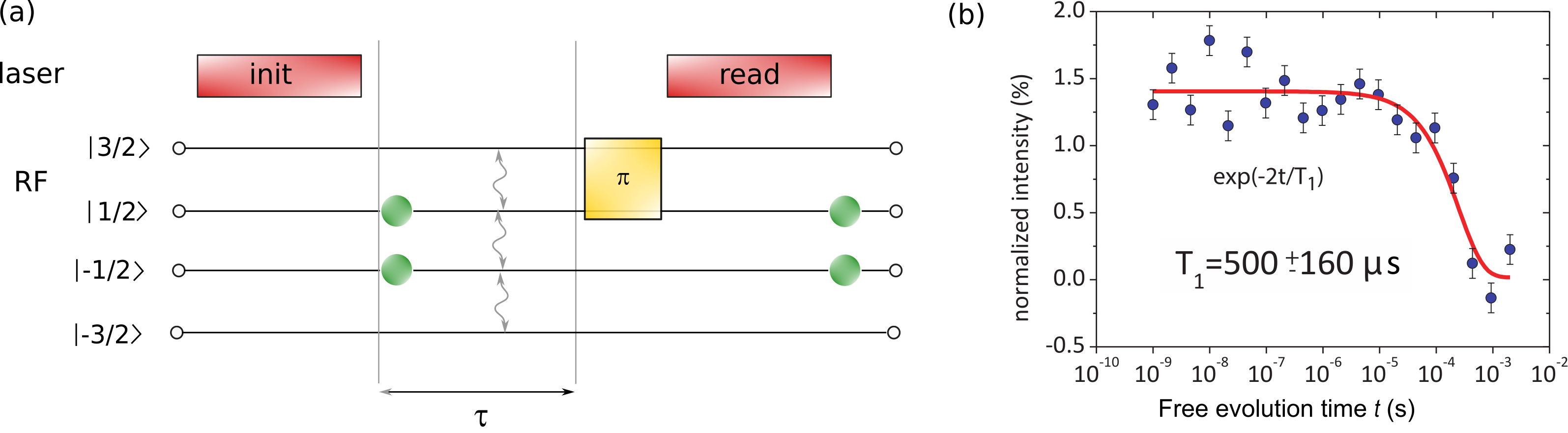
Figure 3.3: a) Pulse sequence for a room temperature T1 relaxation curve. b) Measurement data (blue) and exponential fit (red). Adapted from ref. (Widmann et al., 2015).
A laser pulse with a duration of is used to initialize the system into and with equal probability. The spins will then start to relax into the other states until they are thermally equilibrated. The spin decay curve is obtained by probing the spin state populations. As discussed in Section 3.3.1, a -pulse between and is applied where the time between the laser initialization and the rf-pulse is swept. In that way can be obtained.
The same sequence is repeated to probe the steady state population, however, without applying -pulse. The collected fluorescence signal which will deliver . The obtained T1-curve is plotted in Figure 3.3. The T1-time was determined to be T1 .
Next the quantum state will be further coherently controlled by applying a spin-echo sequence, which will reveal strongly modulated spin collapses and revivals. These irregular patterns are caused by coupling of the electron spin to a nuclear spin bath. To obtain a further understanding of the underlying physics, the next chapter is dedicated to a theoretical workup of a central electron spin coupled to a homo-nuclear spin bath, which is extended to hetero-nuclear spin bath formed by silicon and carbon isotopes.
Spin Pair Dynamics and Coherence
Electron spins are subject to decoherence because of their interactions with nuclear spin environments. For solid state spin systems, multiple mechanisms have been identified as a source for the electron spin decoherence: spin-orbit scattering with phonons (Woods et al., 2002), spectral diffusion due to dipolar interaction of nuclear spins (Anderson & Weiss, 1953), and the hyperfine interaction between electron spin and environmental nuclear spins (A. & J., 2009).
As the spin-orbit coupling is weak for SiC, the noise acting on the electron spin is induced by magnetic fluctuations from parasitic impurities and from fluctuations coming from surrounding nuclei. Assuming a impurity-free crystal, the main source is caused by the nuclear spin bath. As SiC is composed of two different atoms, two types of non-zero nuclear spins contribute to the decoherence of spin defects in SiC, namely Si and C. Their natural abundances are (C) = 1.1 and (Si) = 4.7 .
The electron spin decoherence of the defect in an applied magnetic field is caused by magnetic fluctuations from a large number of surrounding nuclear spins (see Figure 3.4). In particular, the following theoretical results were obtained in a collaboration with the Synergetic Innovation Center of Quantum Information and Quantum Physics, University of Science and Technology of China and is part of a shared publication (Yang et al., 2014).
Spin Hamiltonian
As shown in Figure 3.4 the silicon vacancy electron spin is surrounded by carbon and silicon atoms. The influence of the magnetic fluctuations by these nuclear spins to the electron spin can be described by the following Hamiltonian:
where is the electron spin Hamiltonian of , the internal coupling between the electron spin and the nuclear spins, and describes the nuclear spin bath from the surrounding lattice. A more detailed description of the used Hamiltonian can be found in Appendix: Spin Pair Dynamics.

Figure 3.4: (a) Schematic of the silicon vacancy in 4H-SiC. The c-axis is oriented in the -direction of the crystal. (b) Illustration of the SiC nuclear spin bath. Blue arrows indicate possible and suppressed flip-flop processes between the nuclear spins. Between homo-nuclear spins flip flops are allowed, whereas suppressed among hetero-nuclear spins.
Pseudo Spin Model
The pseudo spin model is composed of two nuclear spins. For homo-nuclear spin pairs at high magnetic fields, the pseudo spin model has been applied to e.g the NV-center in diamond with great success (Zhao et al., 2012). The homo-nuclear spin pair model is illustrated in Figure 3.5. As the Zeeman splittings and are magnetic field strength dependent, they can be lifted using a magnetic field. The large Zeeman splitting decouples the polarized states , and . The resulting pseudo spin is then formed by the remaining unpolarized states, split by a frequency and coupled with a coupling rate . For the hetero-nuclear spin pairs (see Figure 3.5), flip-flop processes are possible among the unpolarized states as in the homonuclear case in (a). However, the vertical component of the hyperfine interaction causes single spin flippings as well. Both spin-flips are equally likely, but are both suppressed in strong enough magnetic fields (Zhao et al., 2012). In the following the two cases (homo and hetero-nuclear spin pairs) are discussed in more detail.

Figure 3.5: and their contribution to the electron spin coherence in strong magnetic fields.a) Energy-level scheme of homonuclear spin pairs. See text for details. b) Energy-level scheme of heteronuclear spin pairs. © 2014 ~American Physical Society. Reprinted with permission from (Yang et al., 2014).
Homo nuclear spin pair dynamics
As above mentioned, at high magnetic fields the pseudo spin is formed by two unpolarized states and , as shown in Figure 3.5a). The other two polarized states and do not contribute to the decoherence (Yang et al., 2014). They can be seen as frozen spins because of the Zeeman-energy difference . The pseudo spin, however, is not frozen. The difference in the hyperfine fields between the coupled nuclei results in a small frequency splitting in the order of kHz, determined by the spatial separation of several of the nuclei.
A weak dipole-dipole interaction between the nuclei results in a transition rate in the order of . The resulting spin flip-flop is caused by this dipole-dipole interaction and appears with a typical period in the order of milliseconds. The electron-spin decoherence can be approximated to . The simulated Hahn echo decay is plotted in Figure 3.5 c), where about 1000 homo-nuclear spin pairs with a cut-off distance of was taken into account.
Hetero nuclear spin pair dynamics
For the hetero-nuclear spin pair case, the system cannot be reduced to a pseudo spin model, because contribution of the polarized states and cannot be neglected any more. The main difference compared to the homo-nuclear case are the differences in the gyromagnetic ratios of each nuclear type. For Si and C the difference is:
In strong magnetic fields ( ) the hyperfine field difference is smaller than the difference between the Zeeman frequencies. Both level splittings and depend on the external magnetic field . Another transition is possible in that case, namely the non-secular transition probability given by ratio of the hyperfine-field differences , perpendicular to the external magnetic field and the splitting of the paired spins :
The probability of the non-secular transition can be larger than that of the secular transition probability . However, at strong magnetic fields both processes are greatly suppressed, because in that case both transitions are: and . The contribution of heteronuclear spins to the electron spin coherence is in fact smaller than in the homonuclear case. At high magnetic fields the spin bath is formed by two independent homo-nuclear spin bath, and because of the larger separation of the contributing baths the electron spin coherence is prolonged by a factor of about two.
For weak magnetic fields, however, both spin types homonuclear and heteronuclear affect the electron spin coherence in a similar way. Opposed to the high-field case, for the hyperfine interaction strength is stronger than the Zeeman splitting. In that case, non-secular spin flips between eg. and become more likely, as the Zeeman-energy is not conserved. The differences between the gyromagnetic ratios are negligibly small and both spins pairs (homonuclear and heteronuclear) act on the central electron spin similary.
Spin Echo Decay
In this section, the spin coherence time was calculated with CCE method (W. Yang & Liu, 2009). The calculation was performed at Beijing Computational Science Research Center in China. The calculated spin-echo decay is plotted as a function of both the external magnetic field and the free precession time in Figure 3.6.

Figure 3.6: a) Hahn-echo for a central spin driven between electron spin levels and plotted as a function of the applied magentic field and versus the free evolution time . b) Hahn-Echo coherence, calculated with distinct CCE orders. c)-e) Hahn-Echo coherence, slices taken from a): in weak c), medium d), and strong magnetic fields c).© 2014American Physical Society. Reprinted with permission from (L. P. Yang et al., 2014).
In Figure 3.6 three different magnetic field regimes can be distinguished: A weak, a medium and a strong field. Such regimes have been found for NVs in diamond as well (Zhao et al., 2012).
Weak magnetic fields
In the weak-field region, where is below the spin coherence decays mono-exponentially within about . In low fields the effective spin bath concentrations for SiC are similar to the NV hence it is not a surprise that the characteristic decay time is similar to the value found in NVs (Zhao et al., 2012).
Medium magnetic fields
Figure 3.6b shows a irregular patterned echo-decay at medium magnetic fields where . Here, the coherence is destroyed already at short times scales of about . The spin revivals at longer times are irregular and the pattern is very sensitive to the nuclear spin orientation in the vicinity of the central electron spin. That pattern is not only remarkably different to the shapes found for NVs in diamond, which are found to be periodically modulated, but also different to systems in SiC (divacancy).
NVs have two non-zero electron sublevels which couple to a single nuclear spin bath. For divacancies in SiC a regular beating pattern is observed. The shape of the revival-pattern depends on the spin bath, and also on the total spin number of the central electron spin. Hence, for divacancies (=1) in silicon carbide, the spin-echo pattern is modulated by the two nuclear Lamor frequencies from Si and C. For the in SiC all four spin sublevels are non-zero and all can couple to the spin bath nuclei. Moreover, these sublevels have different hyperfine couplings to each nucleus, resulting in a modification of their precession frequencies. Depending on the distance to the nuclei, the frequencies are modified differently.
Strong magnetic fields
At high magnetic fields, where , the irregular modulation pattern are very well suppressed, as shown in Figure 3.6 b). The collaps- and revival-effects completely vanish at very high magnetic fields of about . Similar to the weak magnetic field regime, the spin-echo decays mono-exponentially, however, with a very long time constant of more than . That value is twice as long as for the NV in diamond. As before mentioned, the hetero-nuclear spin-flip flop process is greatly suppressed, and is the main reason for the long spin-coherence time.
Zero field and spin bath dilution

Figure 3.7: on Hahn echo at zero field and strong field a) Illustration of the heteronuclear spin influence on the electron spin echo at zero magnetic field. Red solid line represents the spin coherence in a real SiC crystal. Blue dashed line illustrates the effect on the coherence when all Si are replaced by C nuclear spins. Gray dashed-dotted line shows the simulation for C replaced by Si nuclear spins. b) Same calculation as in a) but at strong magnetic fields. © 2014 American Physical Society. Reprinted with permission from (L. P. Yang et al., 2014).
As before mentioned, in strong magnetic fields the spin baths formed by Si and C act as two independent spin baths. That results in a diluted spin bath compared to the homonuclear case and gives rise to the long spin coherence times found in SiC. In order to show that this is the case, the simulation was repeated by replacing Si by C, but keeping other parameters constant. At strong magnetic field the effect is shown in Figure 3.7b). For the homonuclear case, the shortening of the spin-coherence by a factor about 3 further proofs the suggested mechanism for the spin bath dilution.
Additionally the reverse case was simulated by replacing C with Si. A similar effect, comparable to the other replacement, of coherence shortening is seen. That shortening-effect is taken as another confirmation of the spin bath dilution mechanism. The spin bath dilution mechanism can be well explained by additional decoherence channels, which are opened between the initially independent nuclear spin baths.
The effect dominates at strong magnetic fields, but is much weaker at low magnetic fields, as illustrated in Figure 3.7a). In that regime both homo- and heteronuclear spin baths have comparable influence on the coherence times, and further substantiate the dilution mechanism.
Experiment
The coherence time of a single silicon vacancy center was theoretically discussed above, and will be experimentally investigated further. The same spin-defect as in the previous section will be investigated, which cw-odmr spectra and spin-Rabi oscillations was measured and presented in Section odmr and in Section 3.2, respectively. These values are important parameters and prerequisite for pulsed measurements where the spin state needs to be controlled in a precise way.
In particular the resonance frequency for a transition is taken from cw-odmr measurements presented in Section cw-ODMR, and the Rabi sequence is needed to extract the correct pulse length (see Section 3.2). Determination of the appropriate pulse length is mandatory for a correctly applied spin rotation, eg. a rotation of or . Too long or too short pulses incorrect rotation of the spin and the obtained spin-echo does not resemble the correct spin coherence.
The used pulse scheme is presented in Figure 3.8a). A laser pulse is used to initialize the spin state in with equal probability. As mentioned above the frequency is chosen to be resonant between and . An external magnetic field of is applied in order to split the magnetic spin sublevels further, as at zero-field or low-fields the transitions are not well separated for a precise selection. Here, the spin coherence is investigated in the medium magnetic field regime (see Section: medium).
Subsequent to the laser initialization, a fixed waiting time is applied to ensure the complete ground state spin polarization. Consecutively, a -pulse is applied to flip the spin in the - plane of the Bloch sphere.

Figure 3.8: at 270~G and . a) Schematic of the pulse sequence for the Hahn-echo measurement. The spin is initialized into by a laser pulse, a fixed waiting time allows the system to decay into the ground state. A rf pulse with a fixed length () creates a coherent superposition between and . During a variable time delay the spin precesses and is then refocused using a -pulse. After another variable time delay the spin is projected back to the -axis using a , or projected to -axis with the help of a -pulse. The difference between the two obtained intensities PL and PL is normalized by their average and is plotted as an echo intensity as a function of the free precession time in b) at and in c) at . b)-c). Measured Hahn echo decay. Black circles are measurement data. The blue curve is a simulated Hahn echo modulated by the coupling to a proximal Si nuclear spin. d) Simulated Hahn-echo decay at showing strong eseem. Inset shows the a zoom in. From ref. (Widmann et al., 2015).
After the spin rotation, the spin is allowed to evolve in the - plane for a certain amount of time , called the free-precession time . The spin is experiencing a dephasing process during that time, and a -pulse is used to initiate the refocus process with a time duration . To ensure a complete refocus of the dephased spins, the same amount of time is needed, in principle . The subsequent projection pulse is either another -pulse or a -pulse. The -pulse flips the spin back to the origin position , whereas the -pulse rotates the spin into . Essentially the -pulse is an effective pulse, and experimentally realized with a -pulse. After the projection, another laser pulse is used for spin-state readout, which at the same time re-initializes the spin into . The resulting spin-echo decay as a function of the variated free precession time is plotted in Figure 3.8a) and b).
Conclusions and Outlook
In this chapter the coherent properties of a single silicon vacancy center in 4H-SiC were investigated by theoretical and experimental means. It was found that the coherence times of spin defects in SiC can exceed the spin coherence times of spin systems in homonuclear-based hosts, such as NV in diamond. In particular a spin coherence of about was simulated for strong magnetic fields larger than applied along the symmetry axis of the spin defect. Experimentally it was verified that the lower limit of the coherence time is , as the spin coherence did not show a decay up to . These results demonstrate the prospective of operating single electron spin in silicon carbide. One of the criticism to this spin system is, however, the relatively weak spin signal of few percent, which limits the practical use of this system when operated at room temperature. Note, the spin signal can be drastically enhanced up to via resonant optical excitation at low temperatures, which was demonstrated in (Nagy et al., 2018b).
The presented results also are in good agreement to measurements obtained from another spin defect, namely the divacancy in SiC, where a T2 time of for an ensemble of spins at low temperature was achieved (Christle et al., 2015). There the central electron spin possesses (the same as the NV-center in diamond), and only two non-zero magnetic sublevels are able to couple to the nuclear spin bath. The eseem was simulated with the cluster-correlation-expansion method, and was further experimentally confirmed (Christle et al., 2015). The results in (Christle et al., 2015) show also a spin collapse and revival, however with much less irregularities (Seo et al., 2016) and confirmed very well the theory applied in this chapter. Regarding the silicon vacancy, further work was conducted on ensemble at low temperature (Simin et al., 2017). The in (Christle et al., 2015; Seo et al., 2016; Simin et al., 2017) presented results show good agreement with the reported observations in this chapter. In ref. (Simin et al., 2017), the eseem was also found at lower magnetic fields and the nuclear spin flip flop was successfully suppressed at .